Breaking up the Ship of Theseus
I'm a repairer. I enjoy fixing things. Nearly everything I own I've taken apart to a certain extent. Over the years I've come to understand more about this obsession for me and it really comes down to:
- A desire to learn.
- A desire to waste less
- A desire to preserve
My early desire to fix was because of a desire to understand and learn how things were built. Often this is still where the inspiration comes from for me.
The desire to waste less is a secondary reason in many cases. I worry about the garbage we generate daily and wish to reduce my overall impact.
The desire to preserve is a more emotional one, as I think most preservation is. For me often this comes from not wanting to let go. I hold onto objects because I feel an emotional connection to them, they remind me of events or people just the way that scents or photographs do for others. This is part of the reason why I have only owned one car. It's 24 years old now and I have no plans to let it go, I'll just keep fixing it.
As a professional in the field of electronics I also have unique opportunities to repair that most people do not. I am able to talk with experts and learn how to do repairs on complicated electronics myself. This is in some ways no different than learning machining so you can fix something. However there are things that even I cannot fix and indeed nobody on earth can fix: Micro-circuits.
This realization started when I decided I'd really like an iPod classic, 5th generation. I bought a couple broken ones thinking that surely I, a person with experience in electronics design and fabrication, can repair them. However with complicated components failing like amplifiers, processors, etc. and each one being unique and no longer in production, there is little to nothing I can really do short of amalgamating mutliple units together to attempt to create a functioning one. With the complexity of modern solding this is also rather difficult. A board with BGA SMT components on both sides is much more difficult to reflow, as even the manufacturer would have glued the components down to keep them from dropping off. This creates additional complexity as at a minimum flux is required under the components to allow the solder to reflow and wet properly. Clearly this level of complexity, even in the mid 2000's, is not a maintainable level. Not that this is news, but everything is disposable when it has complex microelectronics in it.
I recently asked Jack Ganssle about the recyclability of embedded electronics and if there's been any progress. His answer was no, and that this isn't something that's likely to ever happen. This matches my own thoughts, there just isn't any incentive from governments or consumers to do it. Plus it's a hard problem to solve because of the high level of integration that prevents repairability. Our relentless march for "progress" is a major part of this problem. In the days of 74 series logic it was easy to replace components as they were relatively standard but now devices are frequently made obsolete. This is a major difficulty even in developing new designs, often at work we need to replace obscolete parts even before the design is finished.
I think this is why I often shy away from adding complexity to a project these days. Unnecessary complexity only adds maintenance costs and a likelihood of something failing.
I'm not sure what the answer is since we're in a continual arms race for superior technology. Perhaps it's world peace.
Tags: Writing, Repair, Electronics
Glowing Ball
A simple project that a friend asked me to make for her to fit into her show. Basically she wanted a glowing ball that would mimic the breathing light that apple computers have. Going from a dollar store glow ball to a breathing ball was relatively simple, taking an ATiny micro and a LED RGB chip with built in controller and slapping it all together on some perf board.
Here's what you get for a couple dollars from the Dollar Store:

What you probably can't see is the extreme amount of corrosion on the wires or the fact that there is no insulation on anything. If that LED were to drop down and short across that nut (yes, it is just a nut glued in there) there is a chance for a fire. Personally, I will never buy anything cheap from china anymore, it's just too scary what they will do over there.
After modifying the design and adding in my perf board hack we have:

Not bad. Coating everything real well with hot glue to ensure nothing can come loose and cause a short the final product is this:

The circuit and code is hosted here on github, feel free to do with it as you please. One thing that needs to be changed is adding a 5V boost regulator to keep the voltage constant, as the RGB led chip turns more and more red as the voltage droops lower. As red less generally have lower forward voltage drops, my assumption is that the other LEDs are getting less current and thus the red colouring.
Tags: Circuits, Electronics, Lighting
Model Aircraft Light Controller
Design
As you may or may not know, aircraft flying at night are required to have navigational lights, configured as such. After flying my Hobby Zone Super Cub at dusk and comparing that experience with flying my ParkZone Night Vapour at night, it became clear that having lights on the aircraft would greatly increase usability.
That's how this project was born, an aircraft light controller. Or really, a pulsing circuit.
There are many ways to do this, the first two that come to mind are using a micro, or using a 555 chip. A micro requires a regulated supply, but can do some more interesting things, like changing the frequency based on battery voltage (notice the feature creep starting already). A 555 on the other hand requires no regulation and is very robust. Having a strange affinity for 555 chips that many share, I decided to go with that.
Here's the circuit:
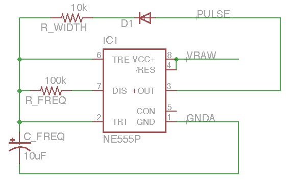
This works by charging the capacitor through the 10k resistor. When it reaches a threshold level, the 555 output goes low. The 100k resistor then is the discharge path. When the capacitor discharges to the threshold point, the output goes high and charges the capacitor. This creates a pulsing waveform, with frequency around 1-2Hz (I didn't measure it) and very nice short pulse widths.
The 555 then controls a 2N3905 NPN transistor that drives the LEDs. Since the entire battery voltage is available, we can have more than a single LED in series, with a simple resistor to control current.
In my design I also added a place to have an "always on" LED so I could add landing lights. Not because they would be helpful, but just because they would look cool.
PCB Manufacturing
Here's a couple pictures of the finished PCB:


The PCB was designed using Eagle and etched using the "PCB Fab-in-a-Box" kit, which works great if you have the time and inclination to etch your own board. I used Feric Acid to etch away the copper. Needless to say, if you're planning on etching your own boards, use proper safety gear! Goggles, gloves, chemical apron, the works!
Circuit
The finished design can be found here. You will likely need to modify resistor values to fit your needs, different supply voltages can affect the frequency, different chips can have different voltage limits, etc. I was also very lazy with the resistors, I have to choose correct ones based on the LED forward voltage and the current I want going through them. That will come.
Eagle Files: Aircraft_lights
Tags: Electronics, Circuits