Beam Robotics
I recently decided to get into BEAM robotics as a fun way to do electronics that was different from my daily job of embedded programming. Solarbotics used to be the main site for BEAM robotics from what I can tell, and they still have an old website up that contains many useful resources on circuits, designs, and just general ideas. Hackaday also recently posted about a Dragonfly beam robot project that someone made. One of the fun parts about BEAM robotics is that the heyday appears to have been in the late 90's to mid 2000's, so resources about it are like walking into a time machine. Plus, for those of us who grew up in that era there is a sense of nostalgia when viewing pages someone clearly wrote themselves.
This is going to be the first of my posts on BEAM robotics as I explore these designs. Mainly my focus lately has been to create a more efficient charging circuit, with the goal of being able to (very slowly) charge a beam robot in regular indoor lighting. Not sure it's possible, but it would be amazing if it was.
This is my first robot, which I've called Iky. The circuit is based off Ken Huntington's Micropower circuit. I've simplified the circuit by removing the need to have a second 2n3904+2x3904 stage for driving the motor and instead am using a single 2n7000 to drive both motor and to provide hysteresis. This works well since the 2n3906 is a current controlled device while the 2n7000 is voltage controlled, which reduces interference that I think was the reason for the extra complication in Ken's circuit. It's probably also possible to make the circuit completely with FETs, but I'm going to leave that for later.
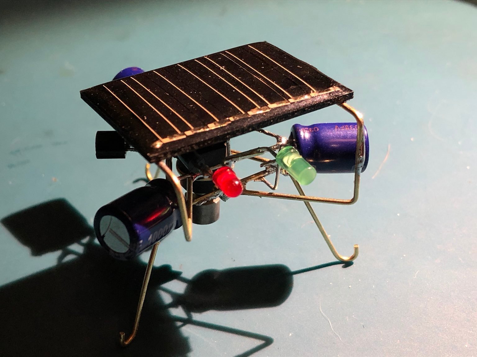
Iky the frightful
To test the performance I used the circuit shown below:

Improved Micropower circuit
| Supply Voltage (V) | Current (nA) |
| 3.072 | 92.0 |
| 3.28 | 230.7 |
| 3.38 | 317 |
| 3.485 | 423.1 |
| 3.586 | 538 |
| 3.687 | 785 |
| 3.74 | 1380 |
| tripped | tripped |
Current vs Applied Voltage
The table above shows that we have a relatively sharp transition point right around 3.7-3.8 V. The granularity here isn't great as I do not have the ability easily change my power supply voltage, so I'm using large steps. Future testing will include automating this measurement so that I can see how "sharp" the trigger is.
I was also able to monitor the trigger point and lowest discharge level of the circuit:
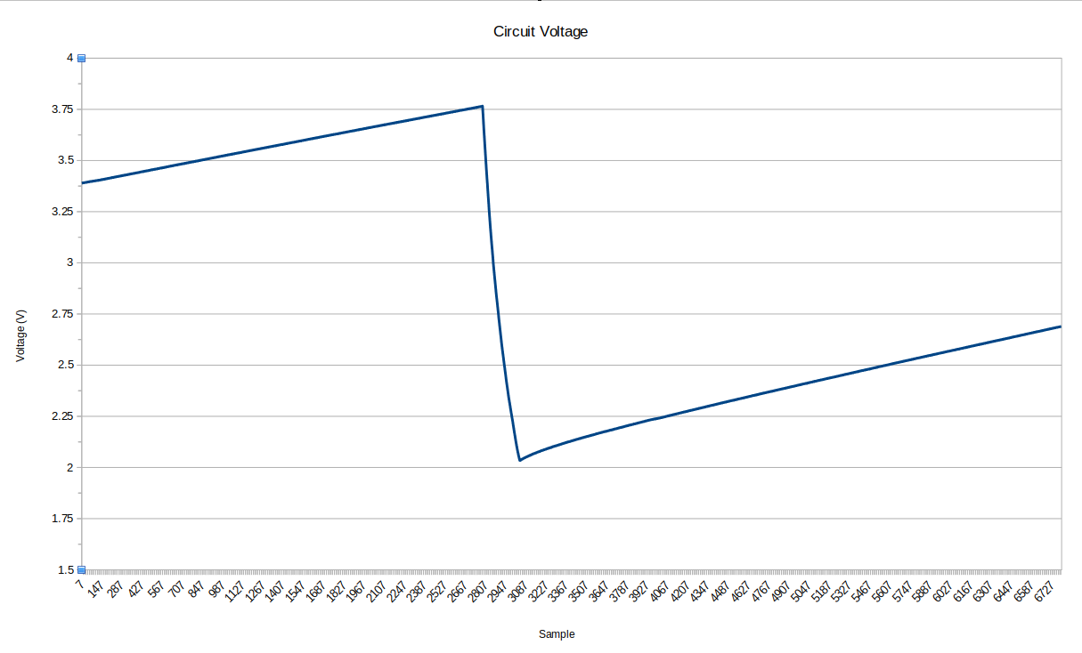
Which shows that the circuit triggered at around 3.75V and would discharge until around 2V. With a 0.01F capacitor storing energy, this means that we store E=1/2CV^2 J or 0.0703J at full charge (3.75V) and have only 0.02J left when discharging stops. This works out to a rather good %72 energy extraction from the circuit.
The main problem I'm left with in this circuit is that when close to the trigger point the consumption increases to >1 uA, which can cause the solar cell voltage to droop when not in direct sunlight, thereby stopping the trigger from activating. I believe this is because the diodes used as a voltage reference / trigger doesn't have a sharp enough "knee" when going from low conduction to high conduction as the capacitor voltage reaches the combined Vf of the diodes. This transition means that the 2n3906's base current isn't sufficient to pull the gate of the 2n7000 high and start the circuit. One thing that could help is having "sharper" transition than the current 1N4148 I'm using in the circuit.
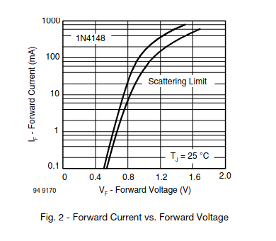
1n4148 Forward Voltage vs Forward Current
I've also attempted to use a darlington pair of PNP transistors (just using two 2n3906's) to improve the gain, but this actually made the transition worse and appeared to consume more current than the previous circuit.
Likely there is also some current lost in the capacitor itself as a parasitic resistance, so further investigation will be required to determine what factors affect the minimum usable current for a BEAM robot. Some other improvements could be in using FETs with lower Vgs requirements, so that the "on-time" of the circuit is better.
That all said I'm very happy with how well it performs for how simple the circuit is.
Tags: Circuits
Reverse Engineering a 7 Segment Display
I recently came across an old five digit seven segment display and decided to see if I could give it a second live. It appears to have been from a weighing device of some kind, judging by the company name: Weigh Right Inc.

It's a gorgeous piece of hand drawn circuitry with lovely smooth lines. There are also very few jumpers on the board so clearly the designer had put in some effort into this single sided design.

The display is essentially a serial to parallel converter, with 5 8bit 74C164 chips driving each digit. Each 74C164 has the 8th bit connected to the following chip to create a single serial interface for the entire display. To understand the design and how to interface to it I traced out the circuitry and drew up the schematic. You can find it on the github page for this project.

After figuring out the binary codes for each segment and building a simple 5V to 12V logic translator with 2N3904 transistors, I wrote up a simple script for an Arduino that would light up all the segments, which was when I found the reason that it was in the scrap pile:

The display functioning, sort of...
Oh dear.
Rather than throw this away I figured I'd see if there was a way to fix it. First step was to figure out if it was the 74C164's. They seemed really hot so I quickly figured out the current for each segment by turning one on at a time and watching the power draw on my bench supply. 18mA. Which if you've read the data sheet for the 74C164 is a tad over the 8mA absolute maximum current of the device. Since I didn't have the original machine that this came from I can't say for sure that the display wasn't being flashed using PWM to reduce the drive current. I can only hope that the original designer didn't miss that. I just reduced the drive voltage from 12V to 8V to get the current down to below 8mA per segment.
After further inspection that all the LEDs were okay on the dead segments I tested the voltage output from the 74C164: 7V, even higher than the lit segments. A bit odd considering the LEDs themselves are fine. Turns out whoever assembled the board decided to save power by putting the LEDs in backwards on a few of the segments! An easy enough fix and now I have a fully functioning 5 digit 7 segment display!

You may notice one LED is brighter than the others. One LED was actually dead and my replacement LED is much newer. Not sure if that's due to technological progress on LED efficacy or just wear (better on the former), but it's quite a big difference! There's another dead LED but somehow it's still conducting current so I might leave it in for now rather than having another strangely bright LED. If I can scavenge a period correct LED (not something I thought I'd ever want) then I might drop it in.
Side note: 1970's Solder smells weird. Not sure if it's the solder formulation, PCB materials, or flux residue.
Next step is just to figure out what to make with it!
Tags: Circuits, Repair, Lighting
Glowing Ball
A simple project that a friend asked me to make for her to fit into her show. Basically she wanted a glowing ball that would mimic the breathing light that apple computers have. Going from a dollar store glow ball to a breathing ball was relatively simple, taking an ATiny micro and a LED RGB chip with built in controller and slapping it all together on some perf board.
Here's what you get for a couple dollars from the Dollar Store:

What you probably can't see is the extreme amount of corrosion on the wires or the fact that there is no insulation on anything. If that LED were to drop down and short across that nut (yes, it is just a nut glued in there) there is a chance for a fire. Personally, I will never buy anything cheap from china anymore, it's just too scary what they will do over there.
After modifying the design and adding in my perf board hack we have:

Not bad. Coating everything real well with hot glue to ensure nothing can come loose and cause a short the final product is this:

The circuit and code is hosted here on github, feel free to do with it as you please. One thing that needs to be changed is adding a 5V boost regulator to keep the voltage constant, as the RGB led chip turns more and more red as the voltage droops lower. As red less generally have lower forward voltage drops, my assumption is that the other LEDs are getting less current and thus the red colouring.
Tags: Circuits, Electronics, Lighting
Replacment License Plate Bulb for CBR250R
A simple project to replace the incandescent bulb that lights up the license plate on my CBR250R bike that keeps burning out. This light and the tail light appear to be more prone to failure, perhaps due to the more rigid connection to the bike than the other lights. I've also been wanting to try and replace lights with LEDs as there is a theory that they provide additional safety due to the fast on times.
The project is really simple, just a PCB that fits into a 168 bulb socket and powers three LEDs with a resistor in series. I want to try and see if i can even do a simple retrofit like this before I think about moving to properly driven electronics. Just sent the boards off to get manufactured, will update once the boards get here.
Project is hosted on -git- (note, removed the file since I can't remember if this version has the fix in it)
(Edit) One thing to watch out for is the polarity of the bulb. I got this wrong and blew the ligth fuse in my bike. No big deal, but a little scary on your new bike haha.
Ring Clock Control Board
Just got some of the boards back from OSH Park and they look great!
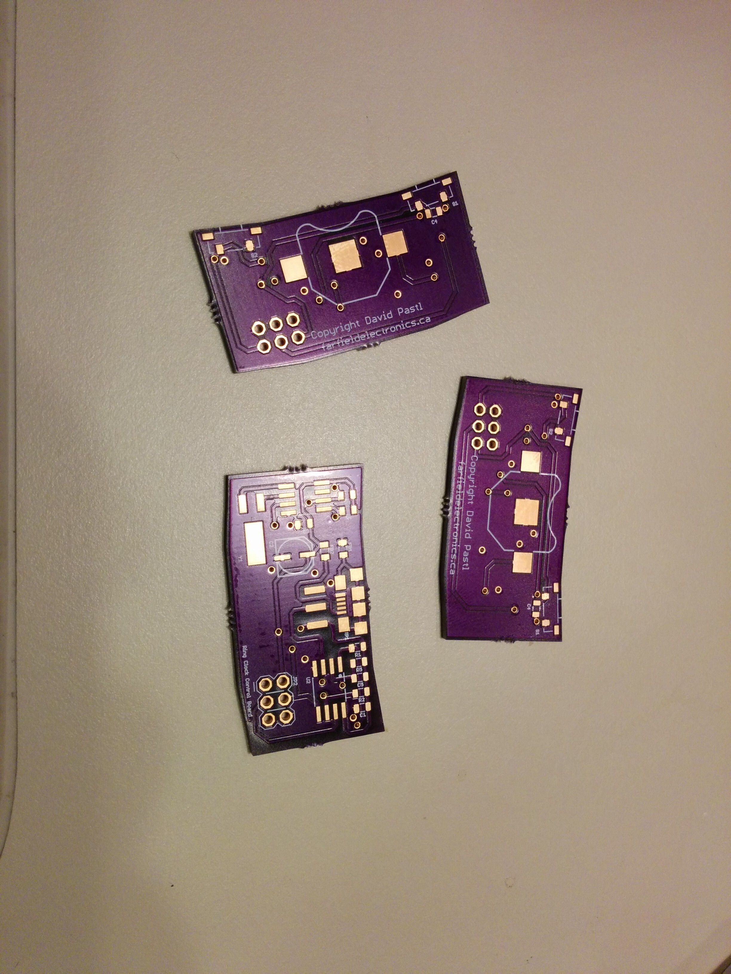
Next step is to get the components and try them out.
In the meantime I found a bluetooth enabled Arduino platform, the Lightblue Bean. This begs the question, would it be better to set the time of the clock with buttons on the clock or with a bluetooth app? I think the coolest solution would be to use capacitive sensors along the perimeter but the cost would be higher than I want with this project at the moment. Thankfully, due to the modularity of the design, I can easily change the control board and upgrade the device whenever I'd like.
More info on the project soon.
Tags: Circuits
Model Aircraft Light Controller
Design
As you may or may not know, aircraft flying at night are required to have navigational lights, configured as such. After flying my Hobby Zone Super Cub at dusk and comparing that experience with flying my ParkZone Night Vapour at night, it became clear that having lights on the aircraft would greatly increase usability.
That's how this project was born, an aircraft light controller. Or really, a pulsing circuit.
There are many ways to do this, the first two that come to mind are using a micro, or using a 555 chip. A micro requires a regulated supply, but can do some more interesting things, like changing the frequency based on battery voltage (notice the feature creep starting already). A 555 on the other hand requires no regulation and is very robust. Having a strange affinity for 555 chips that many share, I decided to go with that.
Here's the circuit:
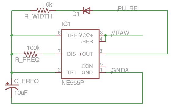
This works by charging the capacitor through the 10k resistor. When it reaches a threshold level, the 555 output goes low. The 100k resistor then is the discharge path. When the capacitor discharges to the threshold point, the output goes high and charges the capacitor. This creates a pulsing waveform, with frequency around 1-2Hz (I didn't measure it) and very nice short pulse widths.
The 555 then controls a 2N3905 NPN transistor that drives the LEDs. Since the entire battery voltage is available, we can have more than a single LED in series, with a simple resistor to control current.
In my design I also added a place to have an "always on" LED so I could add landing lights. Not because they would be helpful, but just because they would look cool.
PCB Manufacturing
Here's a couple pictures of the finished PCB:


The PCB was designed using Eagle and etched using the "PCB Fab-in-a-Box" kit, which works great if you have the time and inclination to etch your own board. I used Feric Acid to etch away the copper. Needless to say, if you're planning on etching your own boards, use proper safety gear! Goggles, gloves, chemical apron, the works!
Circuit
The finished design can be found here. You will likely need to modify resistor values to fit your needs, different supply voltages can affect the frequency, different chips can have different voltage limits, etc. I was also very lazy with the resistors, I have to choose correct ones based on the LED forward voltage and the current I want going through them. That will come.
Eagle Files: Aircraft_lights
Tags: Electronics, Circuits